Boolean Logic
In Boolean Logic, we work with two values: TRUE and FALSE,
customarily encoded as \(1\) and \(0\). Throughout this page we identify the Boolean values with the elements
of \(\{0, 1\}\). This mathematical system is the foundation of digital electronics, computer design, and the
algebraic models studied in computational complexity theory.
Boolean values are combined using the following fundamental operations:
Definition: Fundamental Boolean Operations
- Negation (NOT): \(\neg\)
The negation of a Boolean value is its opposite:
\(\neg 1 = 0\) and \(\neg 0 = 1\).
- Conjunction (AND): \(\wedge\)
The conjunction of two Boolean values is 1 if both operands are 1:
\(1 \wedge 0 = 0,\; 1 \wedge 1 = 1,\; 0 \wedge 0 = 0\).
- Disjunction (OR): \(\vee\)
The disjunction of two Boolean values is 1 if at least one operand is 1:
\(1 \vee 0 = 1,\; 1 \vee 1 = 1,\; 0 \vee 0 = 0\).
More Boolean operations:
- Exclusive Or (XOR): \(\oplus\)
XOR is 1 if exactly one of its two operands is 1:
\(1 \oplus 1 = 0,\; 1 \oplus 0 = 1,\; 0 \oplus 0 = 0\).
- Equality (XNOR): \(\leftrightarrow\)
Equality is 1 if both operands have the same value:
\(1 \leftrightarrow 1 = 1,\; 1 \leftrightarrow 0 = 0,\; 0 \leftrightarrow 0 = 1\).
This is the logical complement of XOR.
- Implication: \(\rightarrow\)
The implication \(P \rightarrow Q\) is 0 only when \(P = 1\) and \(Q = 0\); otherwise it is 1:
\(1 \rightarrow 1 = 1,\; 1 \rightarrow 0 = 0,\; 0 \rightarrow 0 = 1\).
All of these operations are special cases of a more general object: any function from finitely
many Boolean inputs to a single Boolean output.
Definition: Boolean Function
A Boolean function of \(n\) variables (\(n \geq 1\)) is a function
\[
f: \{0, 1\}^n \to \{0, 1\}.
\]
Equivalently, \(f\) is specified by a truth table: a list of the value
\(f(a_1, \ldots, a_n) \in \{0, 1\}\) for each of the \(2^n\) input assignments
\((a_1, \ldots, a_n) \in \{0, 1\}^n\).
Negation of Conjunction & Disjunction
Definition: NAND and NOR
- NAND: \(\uparrow\)
The negation of conjunction:
\[
P \uparrow Q = \neg(P \wedge Q).
\]
NAND is TRUE unless both \(P\) and \(Q\) are TRUE:
\(1 \uparrow 1 = 0,\; 1 \uparrow 0 = 1,\; 0 \uparrow 1 = 1,\; 0 \uparrow 0 = 1\).
- NOR: \(\downarrow\)
The negation of disjunction:
\[
P \downarrow Q = \neg(P \vee Q).
\]
NOR is TRUE only when both \(P\) and \(Q\) are FALSE:
\(1 \downarrow 1 = 0,\; 1 \downarrow 0 = 0,\; 0 \downarrow 1 = 0,\; 0 \downarrow 0 = 1\).
Definition: Functional Completeness
A set of Boolean operations is functionally complete if every Boolean function
can be expressed using only operations from that set.
Theorem: Functional Completeness of \(\{\neg, \wedge, \vee\}\)
The set \(\{\neg, \wedge, \vee\}\) is functionally complete: every
Boolean function
can be expressed as a formula in the variables using only negation, conjunction, and disjunction.
Proof.
Let \(f: \{0, 1\}^n \to \{0, 1\}\). If \(f\) is identically \(0\), then
\(f(x_1, \ldots, x_n) = x_1 \wedge \neg x_1\) suffices. Otherwise, let
\(S = \{(a_1, \ldots, a_n) \in \{0, 1\}^n \mid f(a_1, \ldots, a_n) = 1\}\). For each input
\(\mathbf{a} = (a_1, \ldots, a_n) \in S\), define the minterm
\[
m_{\mathbf{a}}(x_1, \ldots, x_n) = \ell_1 \wedge \ell_2 \wedge \cdots \wedge \ell_n,
\quad \text{where } \ell_i = \begin{cases} x_i & \text{if } a_i = 1, \\ \neg x_i & \text{if } a_i = 0. \end{cases}
\]
By construction, \(m_{\mathbf{a}}(\mathbf{x}) = 1\) iff \(\mathbf{x} = \mathbf{a}\). The
disjunctive normal form of \(f\) is then
\[
f(x_1, \ldots, x_n) = \bigvee_{\mathbf{a} \in S} m_{\mathbf{a}}(x_1, \ldots, x_n),
\]
which evaluates to \(1\) at exactly the inputs in \(S\), matching \(f\).
Remarkably, both \(\{\uparrow\}\) (NAND alone) and \(\{\downarrow\}\) (NOR alone) are functionally
complete. This means that any Boolean circuit can be built from a single type of gate — a fact
exploited in hardware design, where NAND-based logic dominates CPU and memory circuits.
Theorem: Functional Completeness of NAND and NOR
Each of the singleton sets \(\{\uparrow\}\) and \(\{\downarrow\}\) is functionally complete:
every Boolean function can be expressed using only NAND gates, and likewise using only NOR gates.
Proof.
By the functional completeness of \(\{\neg, \wedge, \vee\}\),
every Boolean function can be expressed using these three operations. It therefore suffices to express
\(\neg\), \(\wedge\), and \(\vee\) using NAND alone:
- NOT: \(\quad \neg P = P \uparrow P\)
- AND: \(\quad P \wedge Q = (P \uparrow Q) \uparrow (P \uparrow Q)\)
- OR: \(\quad P \vee Q = (P \uparrow P) \uparrow (Q \uparrow Q)\)
Each identity is verified by direct truth-table evaluation. Since AND, OR, and NOT together
express any Boolean function, and all three can be built from NAND alone, NAND is functionally complete.
The analogous constructions using NOR are:
- NOT: \(\quad \neg P = P \downarrow P\)
- OR: \(\quad P \vee Q = (P \downarrow Q) \downarrow (P \downarrow Q)\)
- AND: \(\quad P \wedge Q = (P \downarrow P) \downarrow (Q \downarrow Q)\)
By the same argument, NOR is functionally complete.
Since every Boolean operation can be written in terms of AND, OR, and NOT, it follows that
every Boolean operation can be expressed using NAND alone. For example:
- Implication:
\[
P \rightarrow Q = \neg P \vee Q = P \uparrow (Q \uparrow Q)
\]
- XOR:
The standard 4-NAND gate construction is
\[
P \oplus Q = (P \uparrow (P \uparrow Q)) \uparrow (Q \uparrow (P \uparrow Q))
\]
- Equality (XNOR):
Since \(P \leftrightarrow Q = \neg(P \oplus Q)\), we negate the XOR construction above:
let \(R = (P \uparrow (P \uparrow Q)) \uparrow (Q \uparrow (P \uparrow Q))\), then
\(P \leftrightarrow Q = R \uparrow R\), using 5 NAND gates total.
Circuits
When we study Boolean logic as a purely mathematical system, the focus is on abstract algebraic properties. However,
when these Boolean functions are implemented in hardware, they are called logic gates.
Computers are built using electronic components wired together in a design known as a digital circuit. Logic
gates are physically implemented using transistors, and each Boolean operation corresponds to a type of gate that controls the
flow of electrical signals.
However, circuits are not only used for physical hardware but also for theoretical models in computer science. When Boolean
functions are used to construct a computational model rather than a physical device, we refer to them as Boolean circuits.
These circuits serve as a fundamental concept in computational complexity theory, where they help analyze the efficiency and
limitations of different computational processes. Here we introduce the basic definition; the study of
circuit complexity — classes such as \(\mathrm{AC}^0\), \(\mathrm{NC}\), and \(\mathrm{P/poly}\) defined by
asymptotic bounds on circuit size and depth — is a subject for future curriculum extensions.
Definition: Boolean Circuit
Fix a functionally complete set
of Boolean operations as the available gate types (typical choices are
\(\{\wedge, \vee, \neg\}\) or \(\{\uparrow\}\)). A Boolean circuit over this gate set is a
directed acyclic graph (DAG) in which each node belongs to one of three categories:
- Input nodes (sources, in-degree \(0\)): each labeled with a Boolean variable.
- Gate nodes (internal): each labeled with one of the available gate types of arity
\(k \geq 1\), with in-degree exactly \(k\); the gate computes that operation applied to its \(k\) input wires.
- Output nodes (sinks, out-degree \(0\)): each producing one final Boolean result.
The size of a circuit is its total number of gate nodes, and its
depth is the length of the longest directed path from any input to any output.
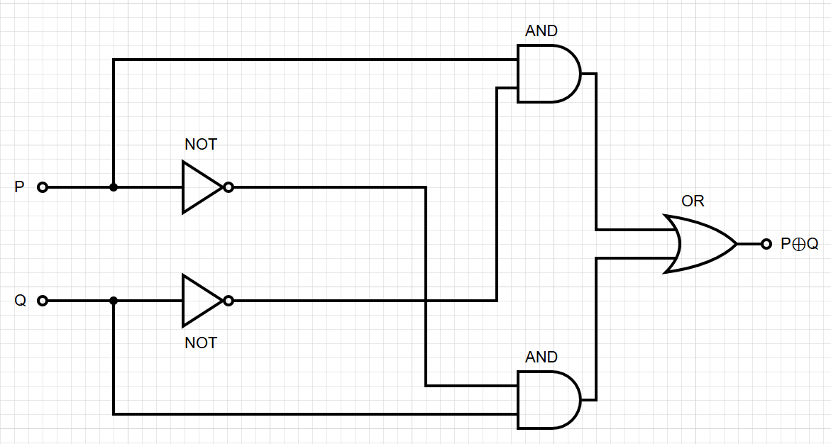
Example: Circuit for XOR
The expression \(P \oplus Q = (P \wedge \neg Q) \vee (\neg P \wedge Q)\)
is realized by the following Boolean circuit using the standard gate set \(\{\neg, \wedge, \vee\}\):
This circuit consists of:
- 2 Input nodes: \(P\) and \(Q\).
- 5 Gate nodes: 2 NOT gates, 2 AND gates, and 1 OR gate. Thus, the size is 5.
- 1 Output node: Producing the final result of \(P \oplus Q\).
The depth of this circuit is 3. For instance, the path \(P \to \text{NOT} \to \text{AND} \to \text{OR}\)
is one of the longest paths, passing through three consecutive gates.
The DAG structure ensures that computation proceeds in a well-defined order from inputs to output,
with no feedback loops. The size of a circuit (number of gates) and its
depth (length of the longest path from input to output) are key measures in
complexity theory.
Boolean logic underlies virtually all of computer science — from the physical transistor level to
the abstract models studied in complexity theory. The operations introduced here appear throughout
the curriculum: XOR is fundamental to finite field arithmetic in abstract algebra,
in cryptography, and Boolean circuits provide a computational model complementary to the
Turing machine.